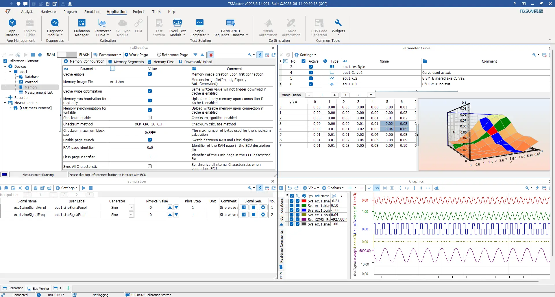
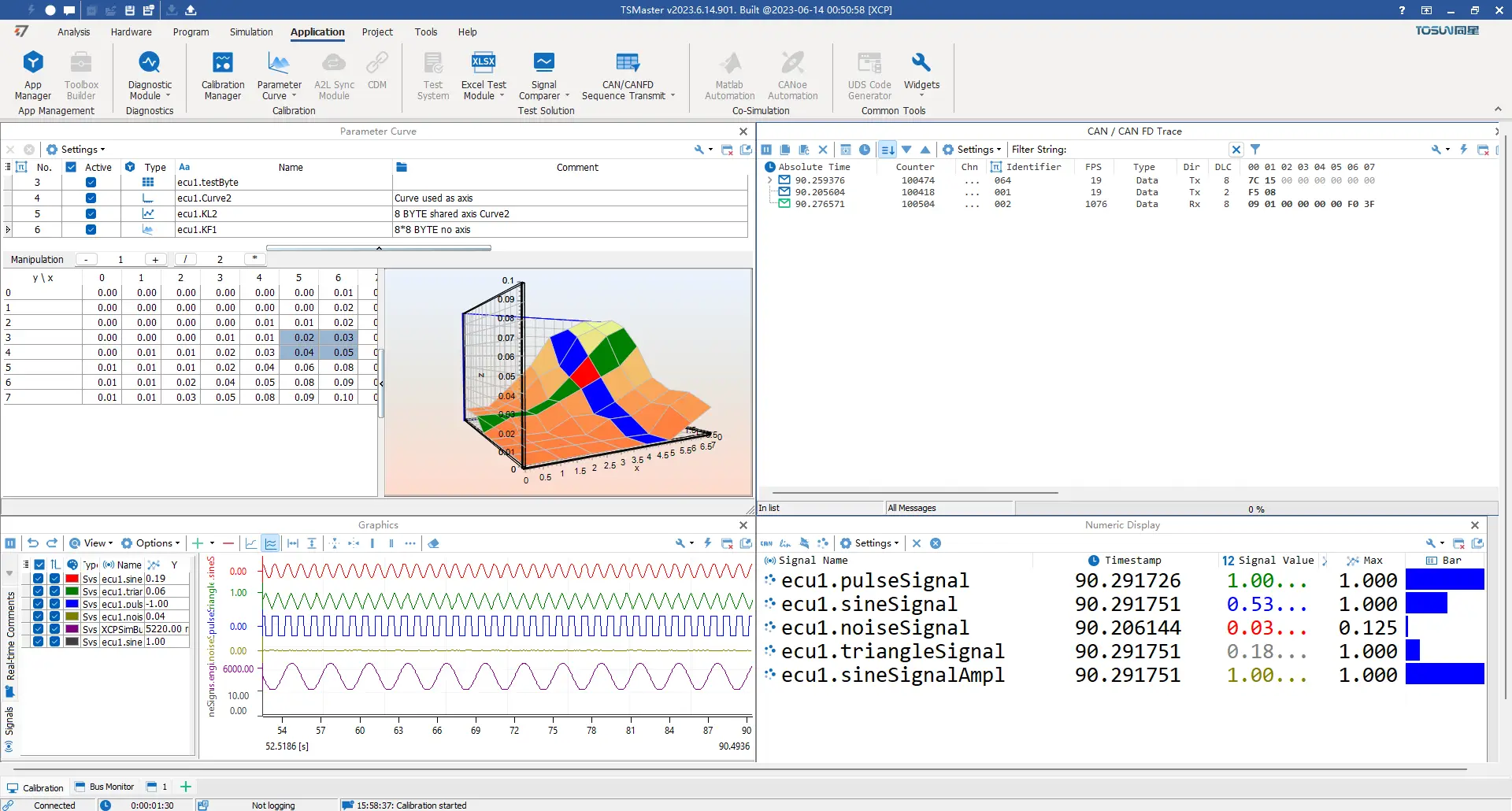
13 Key Features of CCP/XCP Calibration Functionality
- Support for importing A2L files.
- Support for DAQ/Polling measurements.
- Memory settings, including loading image files and configuring
- Verification methods.
- Support for characteristic parameter curves, MAP graphs, etc.
- Storage and playback of MDF/MF4 files.
- Curve representation of graphical variables.
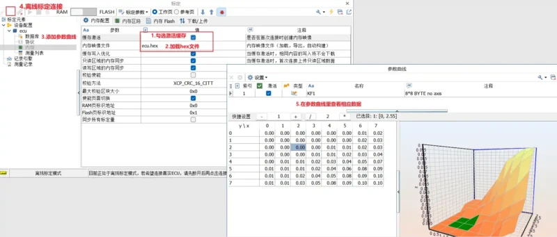
- Calibration parameter management in par or hex formats.
- Integrated message analysis, diagnostics, calibration, and system
- variable data for synchronized data analysis.
- Automation of calibration possible through system variable invocation.
- Support for single-file and multi-file downloads.
- Calibration data management.
FAQ
XCP Calibration part of TSMaster requires a .a2l file as input. How can I do that?
You would need to write your A2L files first, then import them into TSMaster. You can view your signals and observe 8 parameters for free.
If you want to calibrate the parameters, you need to purchase the XCP license.
How to resolve the issue of receiving 'No response on command: 0xFF' when connecting to the ECU using XCP?
This problem primarily involves physical layer connections, calibration configurations, and factors related to the ECU.
- Check the physical connection and channel configuration of the CAN connection channel.
- Ensure that the main identifier ID in the calibration protocol is set correctly.
- Confirm if the ECU itself is functioning properly.
Does TSMaster's XCP support CAN FD? How to configure?
Yes, it supports CAN FD.
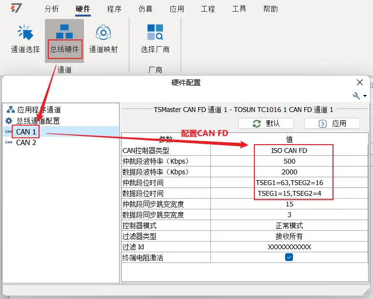
- First, configure the bus hardware, changing it to the corresponding CAN FD baud rate and sample point, for example, 500k+2000k.
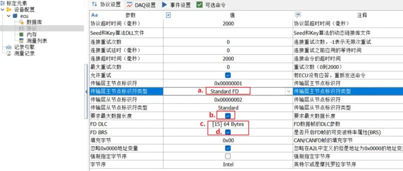
- In Calibration Manager – Protocols, perform CAN FD parameter configuration:
- Transport layer master-slave node identifier type: Change to Standard FD or Extend FD.
- Request maximum data length, enable it.
- FD DLC, choose 64 Bytes.
- FD BRS, check the box.
Does TSMaster support A2L files with version 1.71?
TSMaster is compatible with CANOE’s A2L files, currently supporting version 1.61 only. Future versions will be optimized to support higher versions.
How to resolve the issue of signal stimulation calibration failure after starting online measurement in XCP calibration?
In general, resolving this issue may require remote support to ensure detailed configuration correctness. Here are some suggestions to address the problem:
Ensure that the ECU’s firmware version matches the A2L file and check if the addresses for calibration quantities are correct. It’s essential to record the CAN raw Trace during calibration for comparison and instruction inspection.
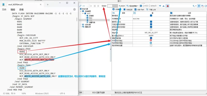
Pay attention to page switching during calibration and understand the difference between RAM and Flash. Typically, calibration pages are located in Flash pages, as indicated in the A2L file.
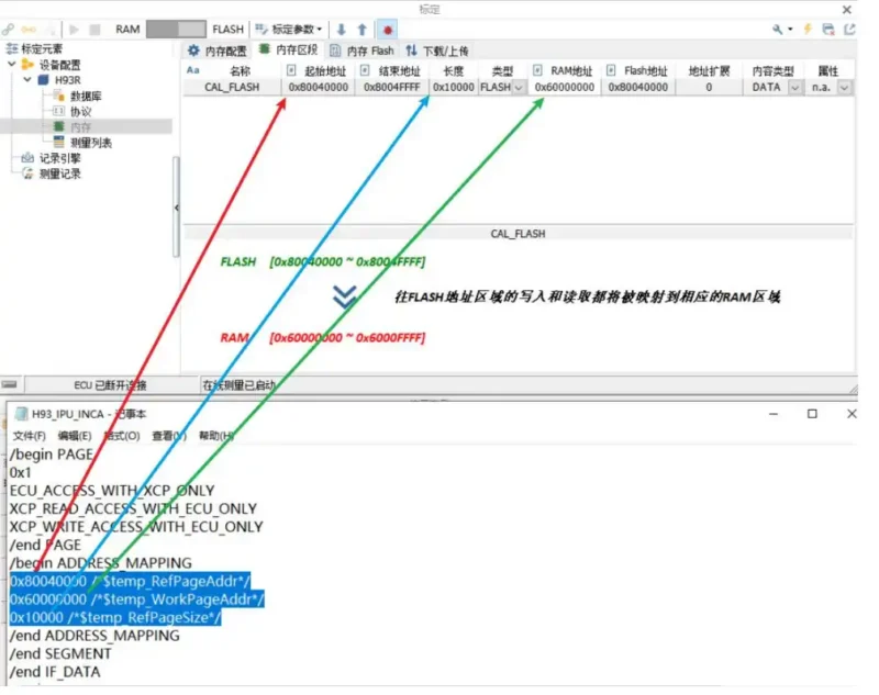
Check for address mapping. If there is mapping, ensure that there are corresponding definitions in the A2L file and that they match in the memory section or Flash memory. Alternatively, manually modify the configuration to match. For example, if the Flash’s starting address is 0x80040000 and is mapped to the RAM area with a starting address of 0x60000000, with a configured length of 0x10000, this maps the Flash address region to the RAM area.

Try replacing the ECU with another known-good one if there is a spare.
If the user has other normal calibration tools like CANape or INCA, compare the calibration configurations in these tools for cross-reference.
Consider recreating the calibration project, re-adding calibration signals, and resetting the signal stimulation window. Sometimes, empty addresses like F6 00 00 00 00 00 00 00 might require reconfiguration.
How to resolve the issue of being unable to calibrate despite connecting to the ECU, initiating online measurement (with valid hardware licenses)?
First, review the message information and check if the request messages (F6) sent during the calibration process are correctly transmitting variable addresses. If the addresses are not transmitted correctly, there may be an issue with the address configuration. Please check the address configuration in the memory section to ensure it aligns with the configuration in the A2L file.
How to address the issue of not receiving upload data and being unable to modify data in the signal excitation interface after the ECU response in XCP calibration?
Typically, if there is no response to the F4 command, it may be due to the use of illegal or abnormal addresses. When using CANape, pay special attention to checking the addresses following the F4 and F6 commands, and there may also be issues related to address mapping.
How to save the modified calibration parameters during online calibration?
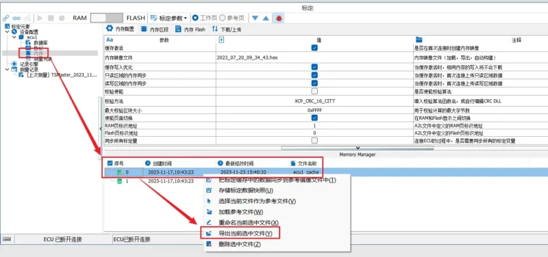
- Enable the cache in ‘Memory’ -> ‘Memory Configuration’ and connect to the ECU. You can view the created memory image file in the Memory manager at the bottom.
- Perform online calibration and modify the relevant calibration parameters.
- In ‘Memory manager,’ select the latest modified image file, right-click, and choose ‘Export the currently selected file.’
- Save it in hex format, which is the calibration workspace file during the calibration process.
